

close
Choose Your Site
Global
Social Media
Improper valve installation acts as a major catalyst for premature system failure. It triggers excessive pressure drops and causes maintenance demands to skyrocket across industrial plants. A poorly placed valve compromises the integrity of an entire piping network. Engineers frequently face a critical choice between standard straight-pattern valves and specialized angular alternatives. An angle globe valve stands out by effectively serving as both a 90-degree pipe elbow and a precise throttling device. This dual functionality drastically reduces the number of required pipe joints and minimizes overall fluid resistance. Our main objective is to provide you with a clear, evidence-based framework. We aim to help piping engineers and procurement leads correctly specify and position these valves within complex fluid architectures. Read on to discover exactly where and how you should integrate them for maximum system reliability.
Angle globe valves are structurally optimized for 90-degree piping turns, replacing the need for a separate elbow fitting and reducing overall pressure drop.
Ideal installation locations include boiler feedwater lines, heater drains, and confined spaces requiring precise flow throttling.
Installation orientation (vertical vs. horizontal) and flow direction (under vs. over the seat) dictate the valve's lifespan and sealing integrity.
Specifying specific variants—such as a bellows angle globe valve or a stainless steel globe valve—is crucial for zero-emission compliance and corrosive media applications.
Standard straight-pattern valves installed near corner junctions create significant engineering headaches. They require extra elbows and additional pipe fittings to navigate corners. This expands your installation footprint unnecessarily. It also increases material requirements and labor time. Crucially, each additional joint introduces a new potential leak point. Over time, these redundant connections invite mechanical stress and vibration-induced failures. Plant managers constantly seek ways to simplify piping geometry. Reducing the number of flanged or welded connections directly improves structural integrity.
You must consider the fluid dynamics at play. A standard Globe Valve paired alongside a separate 90-degree elbow forces the fluid through a highly tortuous path. This configuration generates heavy turbulence. The turbulence creates a high coefficient of friction, leading to severe pressure drops. An angle valve simplifies this internal flow path brilliantly. Fluid enters the body, makes a single sweeping 90-degree turn, and exits efficiently. This streamlined internal geometry significantly reduces pressure drop compared to the two-piece alternative. Less turbulence means less erosive wear on the internal casing.
You should establish clear success criteria before specifying this configuration. Choose an angle design when you face a highly restricted spatial footprint. They excel specifically when operations demand frequent and precise flow throttling. They also prove invaluable when strict industry regulations require minimizing pipe joints in high-pressure systems. By merging two piping components into one solid cast body, you streamline procurement and installation simultaneously. This approach inherently builds a safer, cleaner piping network.
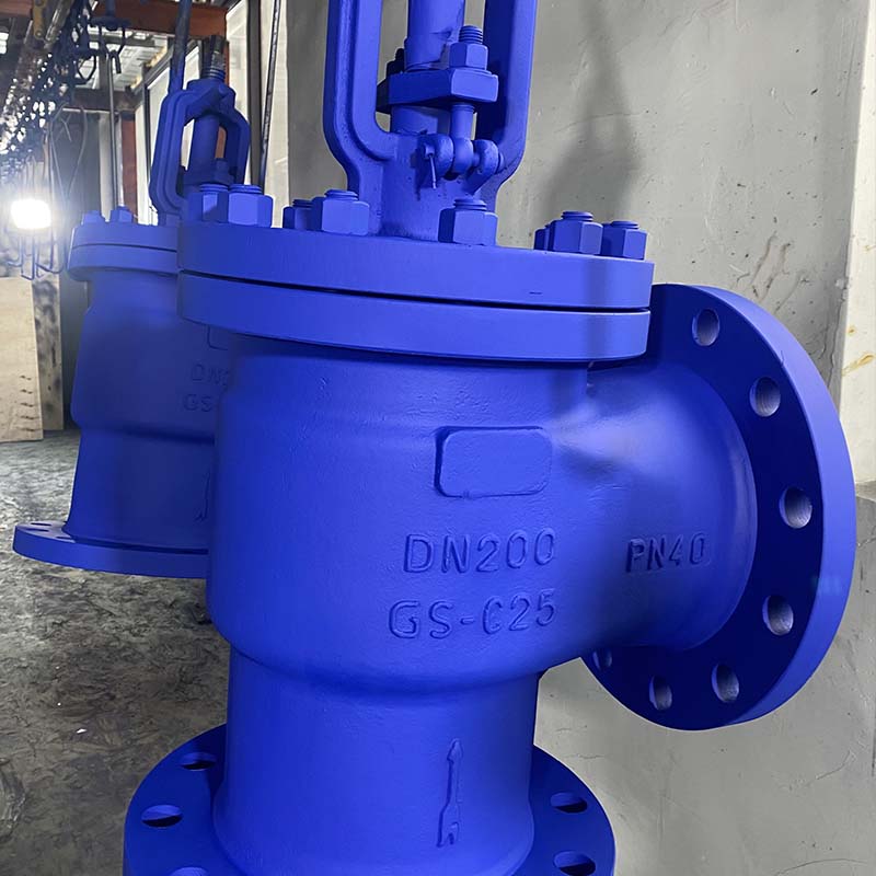
Power generation facilities and heavy industrial steam networks require meticulous component placement. Angle valves serve as the unquestioned standard at boiler feedwater outlets. You will also find them dominating heater drain lines. These specific zones endure extreme pressures and volatile thermal flow conditions. A straight run often induces severe cavitation in these aggressive environments. An angle configuration manages the high pressure differential safely and effectively. It resists the aggressive flashing mechanics. Flashing normally tears apart weaker valve bodies from the inside out. The robust angular body absorbs the kinetic energy of phase-changing fluids better than standard designs.
You must handle vertical-to-horizontal piping transitions with care. Position the valve at the exact point of a 90-degree directional shift. This allows the heavy valve body to act as the primary pipeline elbow. Follow industry standard guidelines for mechanical pipe support. You should anchor the horizontal run directly downstream. This anchoring bears the fluid's kinetic impact as it changes direction. Proper support prevents the valve flanges from acting as load-bearing structural elements. Heavy fluid columns moving vertically downward generate immense momentum. The angle body redirects this force horizontally, provided the adjacent pipes remain fully supported.
Space around industrial pump skids is notoriously tight and unforgiving. Straight-run piping upstream or downstream is often impossible to accommodate. Using angle valves for pump discharge isolation solves this common spatial puzzle. It isolates the pump safely while eliminating the need for a bulky elbow joint right at the discharge nozzle. This compact arrangement gives maintenance teams better physical access to the pump casing. It reduces the cantilevered weight hanging off the pump discharge flange. Less weight means less vibration and longer bearing life for the pump itself.
Carbon steel bodies fail quickly under aggressive chemical attacks. You must evaluate the system's exact medium before finalizing component specifications. Upgrade to a stainless steel globe valve for harsh processing environments. This metallurgical choice offers superior pitting resistance against chlorides and acids. It handles elevated temperature thresholds effortlessly without losing tensile strength. The long-term reliability advantages over carbon steel in corrosive media make it a necessary upgrade. It significantly extends maintenance intervals. It prevents catastrophic body wall thinning, which often leads to dangerous blowouts.
A standard packing gland often falls short in modern chemical facilities. Environmental agencies now enforce incredibly strict zero-leakage mandates globally. When your system handles toxic, flammable, or highly penetrative thermal fluids, you cannot risk minor stem leaks. Here, you must specify a bellows angle globe valve to ensure absolute containment.
The metallic bellows form an impenetrable, accordion-like barrier between the volatile fluid and the atmosphere. This specific mechanical upgrade protects site personnel from dangerous chemical exposure. It meets stringent environmental compliance codes effortlessly. Furthermore, it eliminates chronic packing wear issues caused by continuous stem cycling. You eliminate the need for frequent packing nut adjustments. The bellows absorb the linear stem motion while keeping the fluid entirely sealed within the lower body chamber.
Flow direction dictates valve longevity and operational safety. "Flow under the seat" remains the standard, accepted practice for most applications. In this setup, fluid pressure pushes up directly against the bottom of the disc. When you close the valve, the stem packing becomes entirely isolated from line pressure. This makes the handwheel much easier to open later. It also extends the life of the packing material.
What about "flow over the seat" configurations? This represents a rare exception in piping design. Engineers specify this only for very specific high-pressure steam drop valves. It uses the heavy fluid pressure to hold the disc tightly shut against the seat. However, this subjects the stem packing to continuous high pressure. It increases mechanical risks and makes manual operation physically demanding. You should only use this orientation when directed by specialized thermal engineering plans.
Always install the valve with the stem pointing vertically upward wherever spatially possible. A vertical stem prevents uneven gravitational wear on the internal disc. It keeps the packing rings seated uniformly. Avoid horizontal stem installations at all costs. A horizontal bonnet allows dense debris and particulate matter to accumulate inside the packing chamber. This abrasive debris quickly scores the polished stem. A scored stem causes severe, unrepairable leakage.
An angle valve replaces a standard elbow. However, it is not a structural pipe alignment tool. Never use the heavy valve body to force misaligned pipes together. This terrible practice transfers immense mechanical strain onto the valve flanges. It warps the body casting and ruins internal seat alignment. Outline proper pipe support requirements clearly in your blueprints. Install rigid pipe supports immediately adjacent to the valve. These supports carry the mechanical load of the pipeline, keeping the valve stress-free.
You need a clear decision matrix to select the right fluid control component. Do not guess when specifying valves for critical infrastructure. You can rely on fundamental flow characteristics to guide your choices.
Use a straight-pattern globe design when you have ample straight pipe runs. They work well when system pressure drop limits remain highly flexible.
Choose an angle globe design when space constraints force a sharp 90-degree turn. You need them when you must minimize pressure drop across a corner.
Select an angle seat valve for rapid, high-cycle pneumatic applications. They excel in fast on/off manufacturing environments.
People often confuse angle globe and angle seat terminology. An angle globe features a manual or motor-actuated multi-turn stem. We recommend it for precise, continuous fluid throttling. An angle seat valve uses a pneumatically driven piston lifting off an angled seat. It fits rapid automation processes perfectly but performs poorly in precise throttling.
Valve Type | Primary Application | Actuation Method | Space Efficiency at Corners |
|---|---|---|---|
Angle Globe | Precise multi-turn throttling | Manual Handwheel / Motorized | Excellent (Acts as elbow) |
Straight Globe | General throttling in straight runs | Manual Handwheel / Motorized | Poor (Requires extra elbows) |
Angle Seat | Rapid high-cycle On/Off automation | Pneumatic Piston | Moderate (Often Y-pattern) |
You should follow a structured next-step action plan for procurement. Do not skip these validation steps before issuing purchase orders.
Calculate the exact Cv (flow coefficient) requirements for your specific piping loop.
Verify the required flange pressure ratings against maximum possible system pressure spikes.
Match material specifications strictly to the system media and anticipated temperature ranges.
Review overhead clearance diagrams to ensure maintenance teams can retract the stem fully.
An angle globe valve operates as a highly specialized fluid control component. It is not a universal replacement for all throttling needs across a plant. You deploy it strategically to solve specific geometric and flow dynamic challenges. Correct installation exactly at 90-degree intersections maximizes your overall flow efficiency. It inherently bolsters system safety by reducing unnecessary flanged leak points.
Take proactive action today before finalizing your piping isometric drawings. Consult with experienced valve engineering specialists regarding your layout. Submit your exact system parameters—including pressure, temperature, and media type—for a tailored specification review. Precision at the design stage guarantees decades of reliable, leak-free service from your infrastructure.
A: No, it requires a 90-degree turn in the piping geometry by design. The inlet and outlet ports sit at right angles to one another. Installing it in a straight run would be physically impossible without introducing unnecessary and highly complex pipe routing loops.
A: Yes, installing against the manufacturer's specified flow direction causes severe problems. It triggers heavy cavitation, failure to close tightly, or bent stems. An arrow cast deeply into the valve body dictates the correct flow path. Ignoring this directional arrow compromises system safety entirely.
A: You choose it to eliminate fugitive emissions completely. A bellows seal provides a hermetic metallic barrier. It prevents toxic or flammable media from escaping along the rising valve stem. This ensures strict environmental compliance and keeps plant personnel safe from chemical exposure.
A: You must guarantee adequate overhead clearance for safe maintenance. Technicians need vertical room for full stem retraction, heavy bonnet removal, and repacking procedures. You need enough space to pull the internal components out safely without removing the entire valve body from the active pipeline.


