

close
Choose Your Site
Global
Social Media
Installing a high-pressure globe valve without rigorous pre-installation checks invites severe risks. Engineers often face catastrophic blowouts, premature seat wear, and costly unplanned downtime when skipping vital verifications. In high-pressure pipelines, installation errors are rarely reversible. A flawless installation demands absolute precision and strict adherence to design parameters. You must verify the physical asset strictly matches the Piping and Instrumentation Diagram (P&ID). You also need to validate the mechanical integrity and ensure system readiness before applying any torque to the bolts. This article delivers an evidence-based, engineering-grade checklist. We designed it for execution before integrating any valve into a high-pressure system. Following this operational guide helps minimize your technical risk. It guarantees regulatory compliance while protecting critical infrastructure from sudden, catastrophic failure during process startup phases.
Verify Nameplate & Materials: Ensure pressure-temperature ratings and material composition (e.g., stainless steel) exactly match project documentation.
Confirm Flow Direction: High-pressure globe valves are highly directional; installing them backward can cause severe throttling damage or system failure.
Validate Pre-Testing: Confirm that factory or localized hydrotesting (e.g., API 598) has been completed and documented before line integration.
Assess Bypass Requirements: High differential pressure (ΔP) setups often require bypass lines to safely equalize pressure before operating the main valve.
Evaluating the delivered asset against site requirements remains your primary defense against catastrophic material failure. You cannot rely on visual assumptions when handling extreme pipeline pressures. A rigorous documentation review ensures the physical hardware matches the engineered design perfectly.
First, match the valve tag number against the Piping and Instrumentation Diagram (P&ID). Check the ANSI/ASME pressure class rating cast into the body. Compare the physical flange size directly against procurement specifications. Discrepancies at this stage indicate a fundamental supply error. Installing an improperly rated component creates immediate safety hazards. Do not proceed if the nameplate data contradicts the pipeline engineering specifications. You must quarantine the asset and contact the engineering team for resolution.
Next, you must verify the body and internal trim materials. Industrial processes expose internal components to intense stress. For corrosive or extreme-temperature applications, confirm you have the exact requested alloy. If your design requires a stainless steel globe valve, request the corresponding Mill Test Reports (MTRs). Review these reports to confirm chemical composition and physical yield strength. Additionally, utilize Positive Material Identification (PMI). A handheld XRF analyzer can confirm the exact metallurgy of the valve body on-site. This step prevents catastrophic corrosion failures caused by incorrect factory material substitution.
Systems handling lethal, toxic, or highly volatile fluids require specialized sealing mechanisms. You must verify the specific seal type matches environmental compliance ratings. Standard packing glands often fail under volatile fluid pressure. For example, if the system specifies a bellows angle globe valve, inspect the bellows seal integrity closely. Confirm the asset carries the correct API 622 or API 624 fugitive emission certifications. You should look for specialized trim designs, like Stellite overlays, required for severe service applications. Verifying these specialized elements guarantees compliance with environmental laws and site safety protocols.
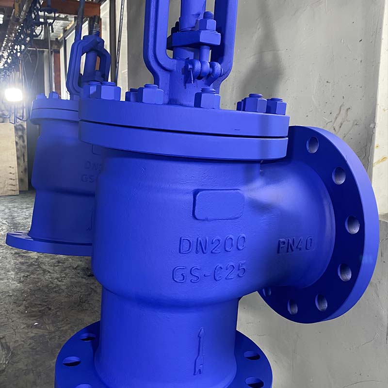
Identifying transit damage, manufacturing defects, or testing oversights before installation saves immense labor. Once technicians bolt heavy equipment into a pipeline, removing it becomes highly disruptive. A thorough physical inspection reveals hidden flaws.
Transit conditions frequently cause hidden physical damage. You must inspect the unit thoroughly before moving it to the pipeline. Follow a structured visual inspection process:
Inspect Flange Faces: Look for scratches, dents, or rust on the sealing surfaces. High-pressure gaskets require flawless surface finishes to maintain a seal.
Examine the Internal Body: Shine a flashlight into the ports. Check for foreign debris. Technicians often find machining chips, dirt, or forgotten desiccant bags inside.
Check Exterior Paint: Ensure the protective coating remains intact. Exposed metal quickly corrodes in harsh industrial environments.
Assess Fasteners: Verify all bonnet bolts remain tightly secured. Look for any signs of thread damage on exposed studs.
Remove any protective end covers only when you are ready for final pipe alignment. Keeping the covers on prevents accidental contamination during site transport.
The internal moving parts require careful mechanical validation. Ensure the threaded stem remains perfectly straight. A bent stem destroys the packing material quickly under high pressure. If the system is safe and depressurized, manually cycle the handwheel. You should feel smooth operation without binding or unusual friction. If the unit features a pneumatic or electric actuator, apply control power to stroke it. Confirm the travel indicator aligns perfectly with the open and closed positions. Any hesitation during actuation indicates internal binding or manufacturing defects.
Never assume a factory component is pressure-ready without documentation. Verify your globe valve passed all required pressure boundary and seat leakage tests. Look for certificates referencing strict standards like API 598. The paperwork must detail the shell test pressure and the exact duration of the seat leak test. You should also check for successful low-pressure air tests. Important Note: Avoid conducting unauthorized field pressure testing. Subjecting the assembly to pressures exceeding the manufacturer's specified limits can permanently deform the internal seat.
Aligning the mechanical components with process flow physics ensures reliable operational control. Incorrect alignment rapidly degrades internal components. Fluid dynamics dictate strict installation parameters.
These components feature highly specific internal flow paths. Fluid direction drastically impacts performance, actuator sizing, and seat longevity. Smaller units typically use a "flow under the plug" (Flow-to-Open) configuration. Large, high-pressure units often require a "flow over the plug" (Flow-to-Close) setup to utilize fluid pressure for tighter sealing. You must check the directional arrow cast directly onto the external body. Installing the unit backward causes severe vibration, rapid cavitation, and ultimate seat destruction.
Table 1: Flow Direction Characteristics in High-Pressure Applications
Configuration | Flow Path | Primary Advantage | Common Application |
|---|---|---|---|
Flow-to-Open (F-to-O) | Under the plug | Promotes smooth throttling; prevents stem slamming. | Small diameter pipes; precise flow control systems. |
Flow-to-Close (F-to-C) | Over the plug | Uses system pressure to maintain a tight seal. | Large diameter lines; extreme high-pressure isolation. |
High differential pressure (ΔP) creates immense challenges during operation. Opening a large plug against a massive pressure differential requires tremendous mechanical torque. Furthermore, cracking the plug open under high ΔP causes a high-velocity fluid jet. This jet causes a "wire drawing" effect, eroding the metal seat instantly. You must verify if the system design requires a bypass line. A small bypass loop equalizes pressure across the main barrier before actuation. Ensure the bypass line is fully installed, tested, and operational before commissioning the main pipeline.
Confirm the final installation angle suits the specific component design. Engineers can technically install these units vertically or horizontally. However, you should ideally orient the stem pointing straight upward. Installing the stem horizontally allows heavy particulates to settle inside the bonnet cavity. This debris buildup scores the stem and causes uneven wear on the packing material. If overhead clearance remains restricted, consult the manufacturer before installing the stem at an angle. Never install the unit upside down, as debris will accumulate directly in the packing gland.
Preparing the surrounding environment protects delicate internal geometry. The finest manufacturing cannot survive poor pipeline hygiene. Clean, aligned piping ensures long-term operational success.
Foreign material represents the greatest threat to a new installation. Weld slag, pipe scale, and dirt cause immediate seat damage. You must validate the adjacent piping is thoroughly cleaned. Standard procedures include high-velocity air blows, water flushing, or steam blows. Ensure technicians remove the main unit and install temporary spool pieces during the flushing phase. Never flush dirty construction debris through a precision control component. Verify the maintenance crew signs off on the pipeline cleanliness certificate before proceeding.
High-pressure piping systems maintain zero tolerance for structural misalignment. You must check the adjoining pipe flanges carefully. They must remain perfectly parallel and concentric. If gaps exist, do not use the flange bolts to pull the pipes together. Forcing a rigid component into a misaligned pipe gap induces dangerous torsional stress. Under high operational pressure and thermal expansion, this induced stress leads to catastrophic body cracking. Use proper pipe supports and rigging to achieve neutral alignment before inserting the unit.
The connection hardware must match the extreme operational parameters. Standard gaskets fail rapidly under severe pressure spikes. Confirm you hold the correct high-pressure gaskets for the specific flange type. Common choices include spiral wound gaskets with graphite filler or solid metal Ring Type Joints (RTJ). Inspect the bolting materials next. You should use high-tensile fasteners, such as ASTM A193 B7 studs, paired with appropriate heavy hex nuts. Ensure all fasteners receive proper lubrication to achieve accurate torque values during the final tightening sequence.
Skipping pre-installation checks shifts the operational risk directly from the manufacturer to your facility. A rigorous validation of materials, physical integrity, flow direction, and system cleanliness protects your heavy capital investment. It also ensures long-term operator safety in hazardous environments. Always verify technical specifications against engineering drawings to prevent costly mismatches.
Once you complete this checklist and the lead engineer signs off, you can proceed to standard installation. Begin standard torquing procedures using a calibrated torque wrench. Always tighten bolts in a designated crisscross pattern to ensure even gasket compression. Finally, move forward with formal system commissioning, knowing your fluid control assets are properly prepared for extreme service.
A: Yes. Flow direction dictates how internal pressure interacts with the plug and seat. Incorrect installation leads to severe vibration, rapid cavitation, and inability to close the unit. It often causes immediate seat destruction. Always follow the directional body arrow cast on the exterior.
A: A bypass line allows a small volume of fluid to pass around the main barrier. This equalizes the pressure on both sides. Equalization reduces the mechanical force required to open the main unit. It prevents the high-velocity "wire drawing" effect that ruins expensive metal seats.
A: While technically flexible, we highly recommend installing them with the stem facing upright. Installing them horizontally or upside down causes process particulates to settle inside the bellows convolutions. This trapped debris leads to premature metal fatigue, cracking, and eventual rupture of the pressure boundary.


