

close
Choose Your Site
Global
Social Media
Improper valve selection in process piping carries severe operational stakes. Facilities routinely risk accelerated trim wear, dangerous fugitive emissions, and crippling system inefficiencies. These issues often stem from unanticipated pressure drops. You simply cannot afford missteps when regulating complex fluid dynamics.
Engineers often regard the standard globe valve as the industry go-to for precise throttling and frequent cycling. However, extreme variations in media properties and demanding pressure classes complicate matters. Strict environmental regulations make off-the-shelf procurement highly risky. Relying on generic specifications quickly compromises system safety and performance.
This guide provides a rigorous technical evaluation framework to standardize your valve selection process. You will discover how to match body configurations to process parameters. We explain how to specify resilient metallurgy and ensure strict regulatory compliance. We outline everything necessary to confidently shortlist vendors and mitigate long-term implementation risks.
Trim design and body configuration must be matched precisely to flow characteristics and allowable pressure drops; there is no one-size-fits-all approach.
Media toxicity and thermal cycling dictate stem sealing requirements, often necessitating specialized designs like the bellows angle globe valve for zero-emission compliance.
Material selection, particularly specifying a stainless steel globe valve versus carbon steel or exotic alloys, must balance upfront capital expenditure against long-term corrosion resistance and lifecycle maintenance.
Vendor shortlisting should prioritize verifiable testing standards (e.g., API 623, ASME B16.34) and localized aftermarket support over initial unit cost.
Engineering teams must define exact operational boundaries before writing specifications. Guesswork leads to catastrophic system failures. You must establish baseline success criteria across four specific technical domains. These metrics form the foundation of a reliable procurement strategy.
You must accurately map the physical operating environment. First, define the absolute maximum and minimum operating pressures. Next, identify the peak operating temperatures. Finally, calculate the expected flow rates and determine the exact Flow Coefficient (Cv) requirements. Oversizing a valve leads to poor low-end control. Undersizing restricts flow and starves downstream equipment.
Fluid properties dictate your metallurgical and sealing requirements. You must classify the media precisely. Is it corrosive, erosive, viscous, or hazardous? Sulfuric acid demands different wetted materials than superheated steam. Suspended particulates require hardened trim materials to prevent rapid erosion.
Determine the primary operational role. Distinguish whether the application requires strict proportional throttling, frequent automated cycling, or secondary isolation. Strict throttling requires specialized plug designs. Secondary isolation prioritizes tight shutoff capabilities. Matching the function ensures seat and plug durability over the equipment's lifespan.
Regulatory frameworks act as non-negotiable filters for procurement. Identify all governing standards for your specific facility. The EPA mandates strict fugitive emission limits for volatile organic compounds (VOCs). API 607 dictates fire-safe requirements for hydrocarbon processing. You must eliminate any configurations failing these minimum compliance thresholds.
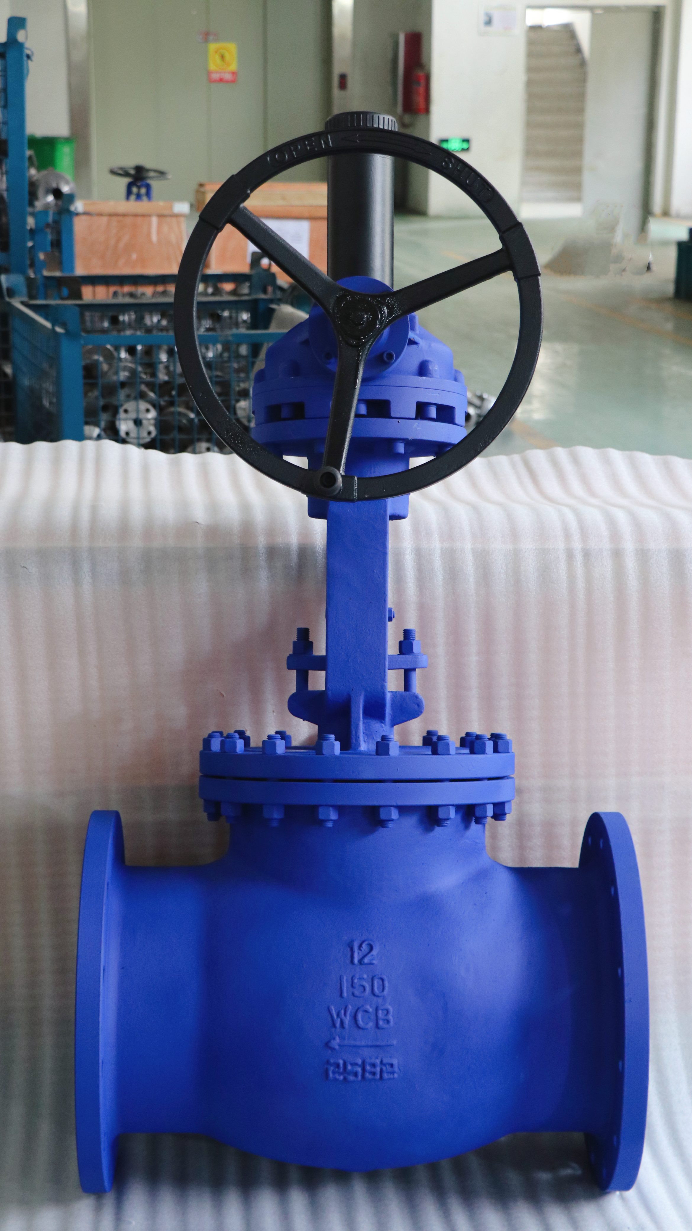
Body geometry directly dictates internal flow resistance. It also determines physical space requirements during installation. Meanwhile, trim design dictates flow control resolution. Let us break down the primary configurations and their engineering tradeoffs.
The Z-body represents the most common straight-through pattern. Fluid enters, moves up through the seat, and exits linearly.
Best for: Standard throttling applications where space allows standard piping runs. It works well when pressure drop is not a critical constraint.
Limitations: It features a high inherent resistance to flow. The tortuous fluid path makes it highly susceptible to cavitation in high-velocity applications.
The Y-pattern straightens the internal fluid path to an approximate 45-degree angle. This significantly reduces turbulence.
Best for: High-pressure applications and critical systems where minimizing pressure drop is essential. It performs exceptionally well in high-pressure steam lines.
Limitations: Maintenance teams find them more complex to service inline compared to standard straight patterns. Accessing the seat requires awkward tooling angles.
Angle patterns combine a 90-degree directional change directly inside the valve body. This geometry eliminates the need for a separate elbow fitting.
Best for: Installations requiring a sharp pipe turn in constrained spaces. It provides a slightly lower pressure drop than standard Z-bodies.
Implementation Use-Case: Specify a bellows angle globe valve for highly toxic or thermal-fluid systems. These systems deem any stem leakage entirely unacceptable. The design utilizes an accordion-like metallic seal. This mechanism completely isolates the dangerous media from the external packing gland.
Plug geometry determines how flow increases as the stem lifts. You must match the plug to your specific control strategy.
V-port Plugs: Deliver fine linear or equal percentage throttling. They excel in continuous control loops requiring precise flow modulation.
Composition Disks: Utilize resilient non-metallic inserts. They provide bubble-tight gas or air shutoff but degrade quickly if used for heavy throttling.
Conventional Parabolic Plugs: Offer moderate throttling capabilities. They serve as reliable general-purpose components for basic flow regulation.
Table 1: Plug Type Performance Comparison
Plug Type | Primary Application | Throttling Precision | Shutoff Capability |
|---|---|---|---|
V-Port | Continuous modulation loops | High (Linear/Equal %) | Moderate (Class IV typical) |
Composition Disk | Pneumatic/Gas isolation | Low (Prone to wear) | Excellent (Class VI typical) |
Parabolic | General fluid control | Moderate | Good (Class IV to V) |
Correct metallurgy prevents rapid degradation. It keeps hazardous media contained safely over the equipment's intended lifespan. You must evaluate materials across the body casing, internal trim, and dynamic seals.
General utility services often rely on standard cast carbon steel. Grades like ASTM A216 WCB or WCC perform excellently for benign, high-temperature applications. They provide robust mechanical strength for standard steam or oil loops.
Corrosive environments demand upgraded alloys. You should evaluate criteria for a stainless steel globe valve (such as CF8M or 316SS) when handling aggressive fluids. Stainless steel resists chloride pitting effectively. It also maintains media purity in deionized water systems. Furthermore, austenitic stainless steels handle extreme temperature gradients, making them suitable for cryogenic applications.
High-differential-pressure services create intense fluid velocities. These velocities strip away standard metals. Assess the operational longevity gained by specifying Stellite or similar hardfacing alloys on seats and plugs. Hardfacing combats wire drawing, which is the severe erosion caused by high-velocity thin fluid streams. It also prevents metal galling when operating at elevated temperatures.
Stem packing prevents fugitive emissions. Compare PTFE against Graphite based on process demands. PTFE offers exceptionally low friction, reducing actuator thrust requirements. However, it possesses a strict lower temperature limit and melts during fires. Graphite withstands extreme heat and remains fire-safe. Unfortunately, graphite creates high stem friction and may require specialized lubrication rings.
Fluid dynamics inside the body create immense destructive potential. Engineers must proactively design systems to mitigate these physical forces. Ignoring these phenomena leads to premature mechanical failure.
Address the inherent flow resistance of this specific valve design. The tortuous fluid path causes significant energy loss. Frame the engineering tradeoff clearly. You gain precise, repeatable flow control. In exchange, you sacrifice pump energy efficiency. Ensure downstream equipment can tolerate the reduced delivery pressure.
Cavitation destroys standard metal trims in weeks. Fluid accelerates through the restriction point, known as the vena contracta. Pressure drops sharply below the fluid's vapor pressure, forming vapor bubbles. As fluid expands into the wider downstream area, rapid pressure recovery occurs. The vapor bubbles undergo violent micro-implosions. These implosions blast shockwaves into the metal, causing severe pitting and mechanical fatigue.
Best Practice: Keep pressure drops below the cavitation index threshold. Consider multi-stage anti-cavitation trim for extreme pressure reductions.
Common Mistake: Relying on standard parabolic plugs for high-pressure letdown stations.
Flashing occurs when media permanently changes to a vapor state post-vena contracta. Unlike cavitation, the downstream pressure never recovers above the vapor pressure. The fluid remains a high-velocity gas-liquid mixture. This mixture acts like a sandblaster. Outline design considerations to mitigate this erosion. Use oversized downstream piping to reduce velocity. Specify aggressively hardened trims and angle-pattern bodies to direct the flashing fluid safely into the pipe center.
Pay strict attention to directional flow requirements. Most designs specify either flow-under-seat or flow-over-seat orientations. Flow-under-seat aids in easy opening and precise throttling. The fluid pressure helps push the plug upward. Flow-over-seat aids in tight shutoff, as the fluid pressure forces the plug into the seat. However, flow-over-seat requires significantly stronger actuation forces to open. Incorrect orientation compromises the actuator sizing and accelerates mechanical wear.
Procurement teams must look beyond initial purchase orders. A strategic vendor selection process guarantees long-term facility reliability. Evaluate manufacturers based on standardization capabilities, certified testing, and logistical reliability.
Limit bespoke configurations whenever possible. Facilities benefit massively from standardization. Standardizing your fluid control assets reduces facility-wide spare parts inventory. It simplifies maintenance training. It also allows maintenance teams to swap components rapidly during unplanned outages. Reserve highly customized geometries only for critical, severe-service applications.
Never rely on marketing claims. Require strictly documented compliance. Mandate adherence to ASME B16.34 to verify accurate pressure-temperature ratings and minimum wall thicknesses. Demand testing data compliant with API 598 for valve inspection and hydrostatic testing.
Assess manufacturer supply chains rigorously. Review vendor lead times for replacement components. Require fully traceable Material Test Reports (MTRs) to confirm chemical compositions. Finally, weigh the logistical advantages of domestic support versus international manufacturing reliability.
Do not solicit bids prematurely. Recommend finalizing the Piping and Instrumentation Diagram (P&ID) parameters entirely. Lock in the precise operating conditions, line sizes, and compliance standards first. Once engineering confirms these specifications, initiate the Request for Quote (RFQ) process with your shortlisted, pre-validated manufacturers.
Specifying a throttling control solution remains a complex engineering challenge. It acts as an exercise in balancing flow control precision against inherent pressure drop and harsh maintenance realities. You must accurately map fluid properties, pressure differentials, and spatial constraints to succeed. Leveraging specialized designs, such as bellows seals or hardened trims, actively prevents catastrophic system failures.
Engineering and procurement teams must align closely on material requirements and compliance standards. Finalize all technical parameters before evaluating manufacturer bids. This alignment guarantees regulatory compliance and avoids costly mid-project redesigns. Prioritize verified manufacturing standards and localized support to secure maximum operational reliability.
A: Flow-under-seat directs fluid pressure beneath the plug. This aids in easier opening and delivers highly precise throttling stability. Flow-over-seat directs pressure above the plug. This configuration assists in achieving tight, leak-proof shutoff but requires a significantly stronger actuator to overcome the pressure when opening.
A: You should specify a bellows design when handling hazardous, toxic, or highly volatile media. The metallic bellows completely isolate the fluid from the stem packing. This guarantees zero fugitive emissions and ensures compliance with strict environmental regulations in high-purity or dangerous applications.
A: Yes, but with limitations. Austenitic stainless steel resists corrosion well, making it suitable for clean steam. However, high temperatures increase the risk of stem and thread galling. For severe high-pressure steam, engineers often specify alloy steels (like F22) or require Stellite hardfacing on the seating surfaces.
A: A standard globe valve typically utilizes manual handwheels or basic on-off actuation for general regulation. A fully automated control valve uses the same internal body style but integrates advanced positioners, smart sensors, and pneumatic actuators. This allows for continuous, dynamic adjustments within automated process loops.


