

close
Choose Your Site
Global
Social Media
High-capacity piping networks form the industrial backbone of modern infrastructure. They rely on strict on/off isolation to keep daily operations safe and moving. Component failure in these harsh environments quickly results in forced downtime. It can also trigger environmental non-compliance or catastrophic safety incidents. Evaluating these components extends far beyond simple diameter checks. You must look past basic pressure classes. Incorrectly matching the wedge design or stem seal to the process fluid creates severe problems. Operators often face thermal binding, fugitive emissions, or rapid seat degradation. The purpose of this guide is straightforward. We provide facility engineers and procurement teams with a clear, evidence-based framework. We will explore how to specify the correct valve architecture across oil, gas, and heavy water applications. You will learn how fluid dynamics, strict compliance standards, and mechanical realities directly shape your best operational choices.
Application matching is critical: Fluid viscosity, temperature fluctuations, and pigging requirements dictate whether a solid wedge or slab gate design is required.
Emissions compliance drives specifications: In gas processing, stem packing is the primary failure point for fugitive emissions, making specialized stem enclosures mandatory.
Gate valves are strictly for isolation: Attempting to use any gate valve for throttling will induce turbulence, cavitation, and inevitable seat damage.
Industrial piping systems demand predictable fluid control. A single incorrectly specified component can compromise an entire processing facility. Understanding the operational limits of your equipment is the first step toward building a reliable system. You must align mechanical capabilities directly to your daily production goals.
You must understand one fundamental rule. These devices serve exclusively as bi-directional isolation barriers. You should only operate them in a fully open or fully closed position. When fully open, they allow unobstructed flow. When fully closed, they provide absolute shutoff. Attempting to use a standard gate valve for flow throttling is a common operational mistake. Partial opening exposes the bottom of the wedge to high-velocity fluid. This induces severe turbulence. It causes a destructive phenomenon known as wire drawing. Over time, high-speed fluid erodes the seating surfaces. This erosion permanently destroys the isolation seal. It also creates extreme vibration, damaging adjacent pipeline supports.
Energy efficiency plays a massive role in large-scale fluid transit. Full-bore designs offer a distinct mechanical advantage. When fully open, the internal port matches the inner diameter of the connecting pipe. Fluid passes through without encountering obstacles. This straight-through path minimizes pressure drop across the pipeline. A lower pressure drop directly translates to reduced pump energy consumption. Over hundreds of miles of oil or water transit, these energy savings accumulate significantly. Facility managers prioritize full-bore designs specifically to lower long-term electrical costs at pumping stations.
Choosing the wrong internal configuration leads to predictable failures. You must anticipate how the process medium interacts with the metal. Common failure modes directly trace back to poor initial specifications.
Seat Scoring: Crude oil and untreated raw water carry abrasive particles. Sand and debris scrape against the metal during actuation. This continuous abrasion scores the seating faces, eventually destroying the seal.
Thermal Binding: Gas processing often involves rapid temperature fluctuations. A solid wedge can expand when exposed to high heat and then suddenly contract during a temperature drop. It gets physically stuck in the closed position. This traps fluid and halts production.
Fugitive Emissions: Traditional packing glands degrade under high-cycle operations. In natural gas processing, worn packing allows volatile organic compounds to escape into the atmosphere. This triggers costly environmental fines and poses severe safety hazards.
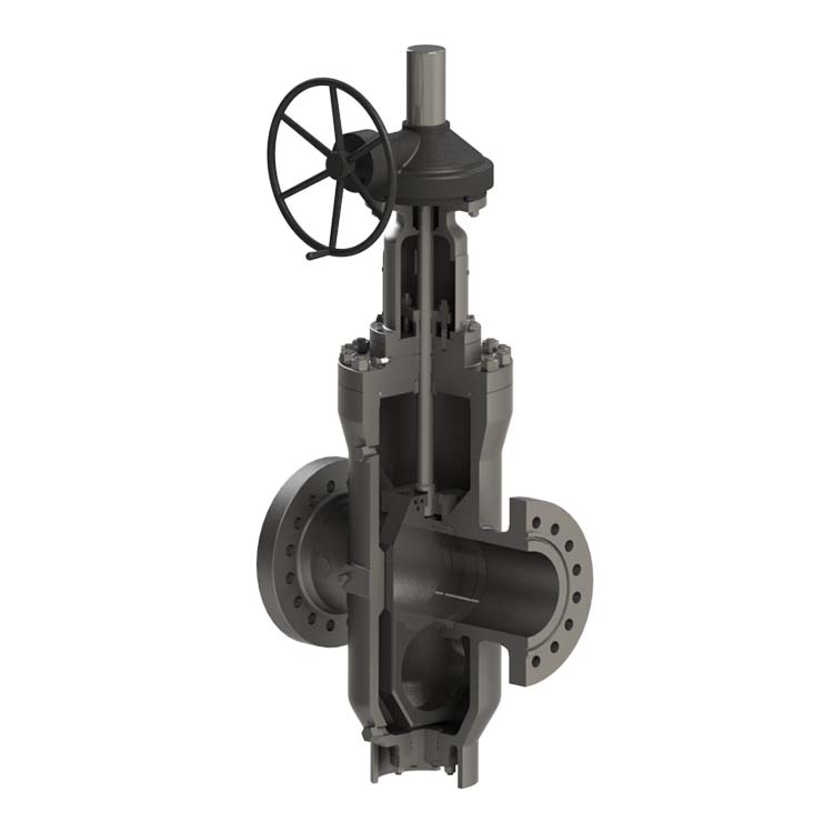
No single mechanical design works for every fluid. You must match the internal architecture to the specific physical properties of the medium passing through the pipe. Viscosity, temperature stability, and pipeline maintenance routines dictate your selection.
This design represents the traditional standard for many industrial applications. Its simplicity provides excellent durability under stable conditions.
The mechanics center around a single-piece, robust machined wedge. Actuation pushes this solid block down between two angled seats to create a tight seal. A solid wedge gate valve offers immense structural strength. It resists deflection under moderate pressure.
These components fit best in moderate-temperature water systems, wastewater treatment plants, and general liquid handling facilities. They excel where fluid dynamics remain predictable. You typically deploy them in environments lacking extreme thermal shocks.
However, this design carries specific limitations. High-temperature pipelines induce rapid thermal expansion. The solid metal block expands tightly against the seats and binds. Operators cannot turn the handwheel to open the line. Furthermore, they are less forgiving of pipe bending or heavy external pipeline loads. External stress easily distorts the seat alignment, causing leaks.
Hydrocarbon pipelines require specialized internal structures. Crude oil and natural gas transit introduce unique maintenance challenges that standard wedges cannot handle.
The mechanics rely on a through-conduit, parallel-faced gate. Unlike an angled wedge, this flat gate remains in continuous contact with the seats during the entire stroke. A hole at the bottom of the gate aligns with the pipe when fully open.
A slab gate valve is strictly mandatory for pipelines requiring routine pigging. Operators frequently send cleaning devices or inspection tools down the pipe. Standard designs feature an open cavity where a pig could easily get trapped. The through-conduit design provides a continuous, smooth internal bore. The pig passes through seamlessly.
This continuous contact protects seating surfaces from abrasive flow wear. It keeps sand and grit away from the critical sealing faces. It also minimizes turbulence in high-velocity transit lines. The parallel seating mechanism accommodates thermal expansion without risking thermal binding.
Toxic and highly flammable gases demand flawless atmospheric sealing. Standard graphite packing eventually leaks. You need a hermetic barrier to ensure absolute safety.
This design replaces the standard stem packing box with a welded metallic bellows. Manufacturers typically craft these from heavy-duty stainless steel or Inconel. The bellows expand and compress like an accordion as the stem moves up and down. A bellows gate valve creates a continuous metal barrier between the fluid and the outside air.
You must specify these for hazardous environments. Hydrogen lines, sour gas (H2S) processing, and dangerous chemical transit require them. Zero-leakage to the atmosphere is often a strict regulatory mandate in these sectors.
The primary outcome is the complete elimination of fugitive emissions. They significantly reduce routine maintenance on packing glands. While the initial procurement cost runs higher, the prevention of gas leaks and the reduction in maintenance labor easily offset the upfront expense.
Procurement teams cannot rely solely on dimensional specifications. Industrial sectors enforce strict manufacturing and material standards. You must verify these certifications before installation to ensure legal compliance and operational safety.
Hydrocarbon extraction and transport subject equipment to extreme pressures and corrosive elements. Compliance revolves around API and NACE standards.
You must verify adherence to API 600 for heavy-duty steel variants. Pipeline installations require API 6D certification. If your facility processes sour gas containing hydrogen sulfide, you must strictly enforce NACE MR0175 compliance. This standard ensures the metal resists sulfide stress cracking.
Material requirements are stringent. Forged steel bodies are standard for high-pressure applications. You must specify specialized trim materials. Stellite hard-facing on the seating surfaces resists high-pressure hydrocarbon erosion. It prevents premature wear during the critical opening and closing phases.
Water distribution networks focus on longevity and contamination prevention. The American Water Works Association (AWWA) dictates these criteria.
You should check for AWWA C500 certification on older, metal-seated designs. Modern systems typically demand AWWA C509 or C515 certification for resilient-seated designs.
Modern water distribution strongly prefers resilient-seated wedges. Manufacturers coat the entire wedge in heavy-duty EPDM or NBR rubber. This rubber layer encapsulates small sand particles and debris during closure. It maintains a bubble-tight seal without permanently damaging the internal metal surfaces.
Corrosion protection is equally critical. You must require Fusion-bonded epoxy (FBE) coatings on both the interior and exterior surfaces. FBE prevents biological fouling. It stops tuberculation and oxidation, ensuring drinking water remains uncontaminated over a fifty-year lifespan.
Table 1: Valve Standard Compliance Criteria
Industry Sector | Governing Standard | Primary Focus | Key Material Requirement |
|---|---|---|---|
Refining / Petrochemical | API 600 | Wall thickness, heavy-duty service | Cast or forged steel, Stellite trim |
Oil & Gas Pipeline | API 6D | Pipeline transit, piggability | Through-conduit designs |
Sour Gas Processing | NACE MR0175 | Sulfide stress cracking prevention | Strict metallurgical hardness limits |
Municipal Water | AWWA C509 / C515 | Bubble-tight sealing, debris handling | EPDM/NBR resilient coating, FBE exterior |
Selecting the right hardware only solves half the problem. Poor installation practices rapidly destroy premium equipment. Engineering teams must evaluate field conditions carefully before finalizing pipeline layouts.
You must accurately assess the torque requirements for seating and unseating. High-pressure lines generate a massive breakaway torque spike when you attempt to open a closed line. Fluid pressure forces the wedge hard against the downstream seat.
Manual Handwheels: Suitable only for smaller diameters and low-pressure systems where operators can physically overcome the breakaway torque.
Gear Operators: Necessary for larger diameters. They provide mechanical advantage, allowing a single operator to safely open high-pressure lines without excessive strain.
Electric/Pneumatic Actuators: Critical for automated facilities. You must match the actuator's torque output to the maximum differential pressure of the system. Oversized actuators can snap the stem, while undersized units fail to open the line during emergencies.
Stem orientation directly impacts mechanical longevity. Engineers strongly advise installing these components vertically, with the stem pointing straight up. Installing them horizontally (with the stem on the side) invites severe trouble.
Horizontal installation causes the heavy wedge to drag along the bottom side of the internal track. This leads to uneven wear and eventual sealing failure. Furthermore, debris in raw water or crude oil lines settles into the horizontal bonnet cavity. It packs tightly around the stem mechanism. This accumulation eventually blocks movement entirely, requiring a costly teardown.
Pipeline layouts must account for future maintenance. Packing materials eventually wear out. You should design piping runs to allow safe access for in-line repacking.
Standard designs often feature a backseat mechanism. When fully open, the stem seals tightly against the upper bonnet. This isolates the packing chamber from the fluid pressure. It allows technicians to repack the gland safely while the system remains pressurized. You must ensure sufficient physical clearance around the installation site for technicians to perform this procedure.
Transitioning from engineering design to procurement requires strict vendor vetting. You must demand documented proof of quality. Do not rely on generic marketing claims.
Look deep beyond the basic spec sheet. Require vendors to submit Material Test Reports (MTRs) for all pressure-retaining components. MTRs trace the exact chemical composition of the steel back to the original foundry. This guarantees the metal meets the required strength and corrosion resistance standards.
Additionally, request documented hydrostatic and pneumatic test results. Every unit should undergo strict pressure testing before it leaves the factory floor. Seat leakage tests verify the internal seal, while shell tests confirm the body can handle maximum pressure without rupturing.
You must evaluate procurement beyond the initial sticker price. Smart engineering teams assess the comprehensive financial impact over a twenty-year horizon.
Hardware and Automation: Calculate the base unit price alongside the required actuation costs. Upgrading to a gear operator adds upfront expense but reduces long-term operational strain.
Component Lifespan: Estimate the expected lifespan of seats and seals within your specific process medium. Abrasive slurries destroy cheaper trims faster, forcing early replacements.
Downtime Expenditure: Factor in the cost of production downtime. If a cheap component fails in a critical hydrocarbon line, the lost daily revenue easily dwarfs the initial savings. Investing in premium trim materials minimizes these shutdown events.
Develop a standardized technical data sheet before contacting vendors. Detail your exact process fluid, maximum and minimum temperatures, maximum operating pressure, and all required API or AWWA certifications. Handing a comprehensive data sheet to a vendor eliminates guesswork. It ensures you receive accurate quotes for equipment capable of surviving your facility's specific operating conditions.
Specifying the correct isolation equipment demands strict attention to detail. It is a necessary balancing act between process demands, safety compliance, and capital expenditure. Overlooking fluid dynamics or thermal variations guarantees early component failure.
Always match the mechanical architecture (solid, slab, or bellows) directly to the specific process medium.
Enforce strict API, AWWA, or NACE compliance to guarantee long-term safety and regulatory alignment.
Avoid horizontal installations to prevent debris accumulation and uneven mechanical wear.
Prioritize long-term operational value over cheap initial unit costs by investing in proper actuation and premium trim materials.
Aligning these technical specifications accurately is the most reliable way to ensure decades of safe, leak-free isolation in high-capacity pipelines.
A: Partial opening causes high-velocity fluid to aggressively erode the bottom of the wedge and the seating surfaces. This destructive process, known as wire drawing, quickly destroys the component's ability to provide absolute isolation. It also induces severe turbulence and structural vibration.
A: A solid wedge consists of a single, robust metal piece best suited for stable temperatures. A flexible wedge features a machined cut around its perimeter. This cut allows the metal faces to flex slightly, compensating for pipe deflection and thermal expansion to prevent the mechanism from binding.
A: You must specify this design whenever the pipeline requires routine pigging for cleaning or internal inspection. The continuous bore prevents the pigging device from getting trapped inside the internal cavity while protecting seating surfaces from abrasive wear.
A: They replace traditional packing with a welded metallic seal. This virtually eliminates the need for routine tightening and replacement of stem packing. It drastically reduces maintenance labor while automatically satisfying strict atmospheric emission monitoring requirements.


