

close
Choose Your Site
Global
Social Media
High-pressure oil and gas piping systems operate under immense stress. Managing severe pressure differentials in these environments leaves zero room for error. Facility layouts often suffer from extreme space constraints. Meanwhile, fugitive emissions remain a strict regulatory hurdle. Engineers face these harsh realities daily. Standard straight-pattern valves often complicate tight plant designs. They require separate pipe elbows to redirect fluid flow. This adds structural bulk and creates potential flanged leak points. The angle configuration offers a highly streamlined alternative. It merges precise fluid throttling and a 90-degree directional turn into one robust unit. This article provides engineers and procurement teams a clear evaluation framework. You will learn how to specify angle globe valves effectively in critical applications. We will explore material choices, seating designs, and installation best practices to optimize your facility's safety and performance.
An angle globe valve eliminates the need for a separate 90-degree pipe elbow, reducing installation footprint and potential leak points.
They provide superior throttling capabilities for high-pressure O&G applications compared to gate valves, with a lower pressure drop than traditional Z-pattern globe valves.
Specifying a stainless steel globe valve or a bellows angle globe valve depends strictly on media corrosiveness and emission compliance requirements (e.g., API 624).
Proper installation (flow direction) and adherence to ASME pressure classes are critical to preventing cavitation and premature seat wear.
Operations suffer significantly when facilities use inefficient piping designs. Pressure drops waste valuable pumping energy. Fluid turbulence triggers pipe vibration. This vibration causes metal fatigue over time. Offshore platforms and pump stations possess very tight physical footprints. Multi-component installations consume this scarce space rapidly. Managing these operational burdens remains a top priority for facility engineers. You must seek integrated solutions to minimize system complexity.
Combining standard straight valves and separate 90-degree elbows introduces severe limitations. This traditional approach creates excessive fluid turbulence. Fluid crashes into the elbow wall before navigating the valve body. Higher wear rates result directly from this aggressive flow path. Furthermore, standard configurations require additional flanged connections. Every extra flange increases the statistical risk of hazardous leaks. These vulnerabilities jeopardize plant safety and environmental compliance.
The angle solution effectively neutralizes these engineering bottlenecks. Manufacturers forge or cast the angle body to serve dual purposes. It functions as both a directional elbow and a precise throttling mechanism. Fluid enters the valve and turns smoothly through the seat. This streamlined path reduces internal turbulence significantly. A standard globe valve usually forces fluid through a convoluted Z-pattern. The angle alternative simplifies this geometry. Engineers benefit from a compact footprint and superior structural integrity.
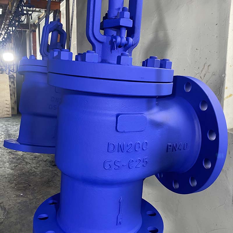
Certain operational environments demand robust structural solutions. Pulsating flow environments subject piping to extreme dynamic stresses. Compressors and positive displacement pumps generate these harsh pulsations. The angle design provides immense structural rigidity. It anchors securely at the corner of a pipe run. This physical orientation absorbs shockwaves better than inline alternatives. Fluid dynamics improve because the valve guides the media through a single controlled turn. You experience less mechanical degradation during prolonged operations.
Choke manifolds and heater treaters rely heavily on these specific valves. High-pressure crude oil and gas enter separation equipment through precise throttling points. Flow regulation must remain exceptionally accurate here. Angle configurations handle these volatile pressure drops gracefully. They manage the rapid expansion of gases entering the separation chambers. Operators gain precise control over production volumes entering the treatment phase.
Pump discharge systems and boiler feed lines represent another critical application area. High-pressure discharge requires immediate flow modulation. Piping designs frequently require a 90-degree turn directly after the pump nozzle. An angle valve fulfills both the directional and throttling requirements structurally. It prevents backward flow when integrated properly into the control loop. High-pressure steam routing relies on this efficiency to maintain safe boiler operations.
Engineers must acknowledge one crucial skeptical caveat. You should not use these valves everywhere. Applications requiring zero pressure drop demand different equipment. Full unobstructed flow lines require gate valves or ball valves. Throttling designs inherently restrict flow to modulate pressure. Placing an angle valve in a pure isolation line causes unnecessary energy loss. Always match the valve type to the primary operational intent.
Handling corrosive environments dictates strict metallurgical choices. Operators frequently debate using carbon steel versus stainless steel. Sour gas contains deadly hydrogen sulfide (H2S). This compound aggressively attacks standard carbon steel components. You must evaluate the operational risks associated with sulfide stress cracking. Specifying a stainless steel globe valve provides critical resistance. Alloys like 316SS or Duplex stainless steel withstand harsh chemical degradation. Framing this decision around NACE MR0175 compliance ensures operational safety. Investing in superior metallurgy prevents catastrophic blowouts in sour service lines.
Environmental agencies heavily penalize fugitive emissions. Zero-fugitive emission requirements now dominate modern facility planning. Highly toxic or volatile media require specialized sealing technologies. We introduce the bellows angle globe valve as the definitive regulatory solution. Traditional graphite packing inevitably wears down through repeated stem cycling. This wear allows microscopic vapor leaks. A metallic bellows seal changes this dynamic completely.
The bellows mechanism entirely isolates the internal stem from the fluid media. Manufacturers weld an accordion-like metal tube around the lower stem section. This barrier flexes as the operator opens or closes the valve. It traps volatile organic compounds (VOCs) securely inside the pressure boundary. This technology eliminates packing leaks almost entirely. It reduces environmental compliance risks dramatically.
We must acknowledge the trade-off transparency regarding this technology. Bellows seals carry a higher upfront acquisition cost. Their internal construction involves complex engineering and precision welding. Maintenance requires specialized training compared to repacking standard graphite seals. If the bellows rupture, the valve relies on secondary backup packing. You must weigh these complexities against strict local emission penalties.
Selecting the correct unit requires deep technical scrutiny. Pressure class and body construction dictate the fundamental safety limits. You must match the ASME B16.34 pressure classes precisely. Standard choices include Class 900, 1500, or 2500 for high-pressure service. We strongly recommend forged bodies over cast bodies for ultra-high-pressure applications. Forging eliminates internal porosity and microscopic voids. This integrity proves essential when handling explosive media.
Disc and seat design determines control accuracy. O&G media frequently contains suspended solids like sand or debris. The valve internals must withstand this abrasive flow.
Disc Type | Control Precision | Solid Tolerance | Best Application |
|---|---|---|---|
Plug Disc | Moderate to High | Excellent | General throttling and heavy crude service. |
Composition Disc | Moderate | Poor (susceptible to tearing) | Clean gases or low-temp utility air. |
Needle Disc | Extremely High | Fair | Fine flow regulation in clean chemical injection. |
Flow characteristics define how the valve reacts to actuator commands. Selecting the correct trim proves vital for plant stability. A linear trim increases flow proportionally to stem travel. An equal percentage trim increases flow exponentially. You must match this characteristic to the control loop requirements. Proper matching prevents erratic flow surging. Every Globe Valve requires careful trim calculation to ensure smooth operations.
Industry standards provide operational authority. You must verify adherence to API 623 for robust structural design. This standard mandates heavier wall thicknesses and stronger stems. Additionally, API 598 dictates rigorous valve inspection and testing protocols. Manufacturers must perform high-pressure hydrostatic tests before shipping. Requesting these testing certificates guarantees compliance and mechanical reliability.
Field implementation exposes distinct mechanical risks. Flow direction nuances command immediate attention during installation. Engineers face a critical decision regarding media routing. The choice between "flow under the seat" and "flow over the seat" alters performance entirely.
Consider the following best practices for flow direction:
Flow under the seat: Standard for smaller lines and lower pressures. It allows easier manual operation and protects packing from continuous high pressure.
Flow over the seat: Often required for high-pressure steam. The media pressure helps seal the disc tightly against the seat. It provides a reliable failsafe state.
Cavitation and flashing destroy internal components rapidly. High-pressure drops cause liquid media to vaporize temporarily. These vapor bubbles collapse violently as pressure recovers. The resulting micro-jets blast metal away from the seating surfaces. We strongly recommend hardened trim materials to mitigate this severe erosion. Stellite overlays applied to the plug and seat ring extend operational life. These cobalt-chromium alloys resist cavitation damage exceptionally well.
Maintenance accessibility frequently haunts facility operators. Tight corners restrict physical tool movement. You must factor in the vertical space required to remove the bonnet assembly. Technicians need clearance to extract the stem and replace internal trims. They must perform this without removing the massive valve body from the pipeline. Pre-planning these maintenance clearances prevents costly extended shutdowns later.
Angle globe valves function as highly specialized tools in hazardous environments. They expertly combine structural directional changes with precise fluid throttling. High-pressure O&G systems benefit immensely from this consolidated design. Removing elbows reduces leak risks and shrinks facility footprints.
Buyers must apply strict shortlisting logic during procurement. Prioritize flow data calculations (Cv) to ensure accurate control. Assess media toxicity carefully; dangerous gases necessitate bellows seals. Evaluate environmental corrosiveness rigorously; sour gas demands robust stainless steel metallurgy. Comparing manufacturer quotes against these specific criteria guarantees optimal performance.
Take immediate action by consulting your piping and instrumentation diagrams (P&ID). Identify awkward elbow-valve combinations currently causing vibration or pressure loss. These bottlenecks represent prime optimization opportunities. Request a technical consultation with a reputable valve manufacturer to discuss customized angle solutions for your facility.
A: A standard globe valve features a straight, Z-pattern flow path requiring inline installation. An angle configuration redirects fluid precisely 90 degrees within the body. This unique design eliminates the need for a separate pipe elbow. It generally offers a lower pressure drop and improved resistance to pulsating pipe vibration.
A: You should specify a bellows seal when handling highly hazardous, toxic, or regulated O&G media. The metallic bellows completely enclose the stem, physically blocking fluid escape. It serves as the primary defense when stem leakage or fugitive emissions are strictly unacceptable under environmental laws.
A: Yes, they offer excellent shut-off capabilities. Their mechanical design forces the plug tightly against the seat ring, creating a secure seal. However, engineers primarily deploy them for fluid throttling and flow modulation rather than pure on/off isolation tasks.
A: Stainless steel provides superior resistance to extreme temperatures and highly corrosive media. Facilities processing sour gas (H2S) rely on alloys to prevent sulfide stress cracking. Additionally, stainless steel withstands harsh exterior offshore environments, preventing external rust and ensuring a longer operational lifecycle.


