

close
Choose Your Site
Global
Social Media
Modern steam systems demand precise flow regulation and uncompromising leak prevention. Plant operators require this strict control to maintain peak thermal efficiency and facility safety. Without reliable regulation components, industrial facilities face constant operational hazards.
Incorrect valve selection in steam lines leads directly to equipment failure. It causes premature seat wear, commonly known as wire drawing, and creates dangerous high-pressure steam leaks. These poor choices ultimately result in highly erratic temperature control across the plant.
As the industry standard for linear motion throttling, the industrial globe valve solves these specific challenges. Manufacturers engineer them specially to handle severe pressure drops. You can rely on them to deliver the exact flow calibration required in heavy-duty steam applications.
Globe valves provide superior throttling and frequent-operation capabilities compared to gate or ball valves in steam networks.
Selecting the right body pattern and seal type (e.g., bellows seal) mitigates fugitive emissions and pressure loss.
Material specification is critical; high-temperature or corrosive condensate environments often necessitate a stainless steel globe valve.
Proper sizing (Cv calculation) and installation orientation are required to prevent water hammer and internal erosion.
Industrial piping networks rely on specific valve designs for distinct operational tasks. Operators often mistakenly attempt to use standard isolation valves for flow regulation. This choice quickly degrades system integrity. Let us examine exactly why specialized throttling valves outshine basic alternatives in steam services.
The linear motion design provides unmatched proportional flow control. Inside the body, a machined plug moves linearly down toward a stationary seat ring. This plug-to-seat relationship allows operators to adjust the opening size meticulously. You can calibrate the exact volume of steam passing through the pipeline. Quarter-turn alternatives, like ball or butterfly designs, simply cannot match this precision. They often create turbulent flow streams. Linear designs ensure predictable, smooth volume adjustments across the entire stroke length.
High-velocity steam carries immense destructive energy. When operators crack open a standard gate valve to throttle flow, steam rushes past the sealing surfaces. This extreme velocity carves microscopic grooves into the metal. Engineers call this phenomenon "wire drawing." The internal geometry of a globe design intentionally protects the seating surface. The fluid must change direction inside the chamber. This directional shift dissipates kinetic energy before the steam crosses the sealing boundary. It preserves the plug and seat integrity over thousands of cycles. Gate designs lack this protective geometry entirely.
Every engineering advantage introduces a necessary trade-off. We must transparently acknowledge the primary drawback here. These valves generate a higher pressure drop, also known as head loss. The fluid must navigate an S-shaped flow path inside the standard body. It turns 90 degrees upward, passes through the seat, and turns 90 degrees again to exit. This tortuous path inherently restricts fluid momentum. System designers must account for this pressure reduction during the initial sizing phase. They compensate by adjusting boiler output pressure or selecting larger downstream piping.
Gate Alternatives: Excellent for isolation, terrible for throttling due to instant wire drawing.
Ball Alternatives: Prone to thermal binding under rapid steam expansion.
Linear Throttling: Provides the only reliable, repeatable method for modifying steam volume without destroying internal components.
Manufacturers do not produce a single, universal model. They engineer various body patterns to solve specific piping layout challenges. Selecting the correct geometry ensures optimal thermal performance.
The Z-body represents the most common configuration in industrial facilities. Fluid enters horizontally, moves upward through the central web, and exits horizontally. It looks somewhat like the letter Z internally. This straight pattern works best for severe throttling duties. The internal restriction provides incredibly accurate flow modulation. Engineers specify this pattern when pressure drop serves as an acceptable trade-off for absolute precision. You will typically find these units controlling steam flow into heat exchangers or jacketed reactors.
Continuous steam lines require minimal flow resistance. The Y-pattern angles the stem and bonnet at roughly 45 degrees to the pipeline. This oblique internal web significantly straightens the fluid path. Steam flows through the chamber much more efficiently compared to the standard Z-body. Engineers rely on the Y-pattern to minimize pressure drop while preserving excellent throttling capability. It provides a perfect middle ground for long-distance steam distribution headers.
Complex piping configurations often require specialized solutions to manage both flow direction and emissions.
Angle pattern benefits: An angle configuration features inlet and outlet ports set exactly at right angles. It functions simultaneously as both a throttling mechanism and a 90-degree pipe elbow. This dual functionality drastically reduces installation complexity. It eliminates the need for extra welded pipe fittings. Furthermore, this pattern offers less fluid resistance than standard straight models, mitigating head loss.
Bellows seal mechanism: Fugitive emissions present massive safety hazards in high-pressure steam lines. Standard packing glands inevitably wear down and leak. A bellows angle globe valve uses a flexible metallic bellows cartridge. Manufacturers weld one end to the stem and the other to the bonnet. This totally isolates the moving stem from the hot steam fluid. It guarantees absolute zero fugitive emissions. You must utilize this technology for hazardous, toxic, or exceptionally high-pressure steam environments.
Table: Pipeline Pattern Configurations
Design Profile | Primary Engineering Benefit | Ideal Industrial Application | Inherent Fluid Resistance |
|---|---|---|---|
Standard Z-Body | Maximum throttling precision | Heat exchangers, strict flow control loops | High |
Oblique Y-Pattern | Straighter flow path, energy retention | Continuous distribution lines | Medium |
Angle Configuration | Replaces elbows, lowers joint count | Piping corners, boiler discharge points | Low to Medium |
Material science dictates the ultimate success or failure of any steam piping network. Selecting inappropriate metal alloys leads to catastrophic structural failures. Plant engineers must match the material grade to the specific thermal and chemical properties of the internal fluid.
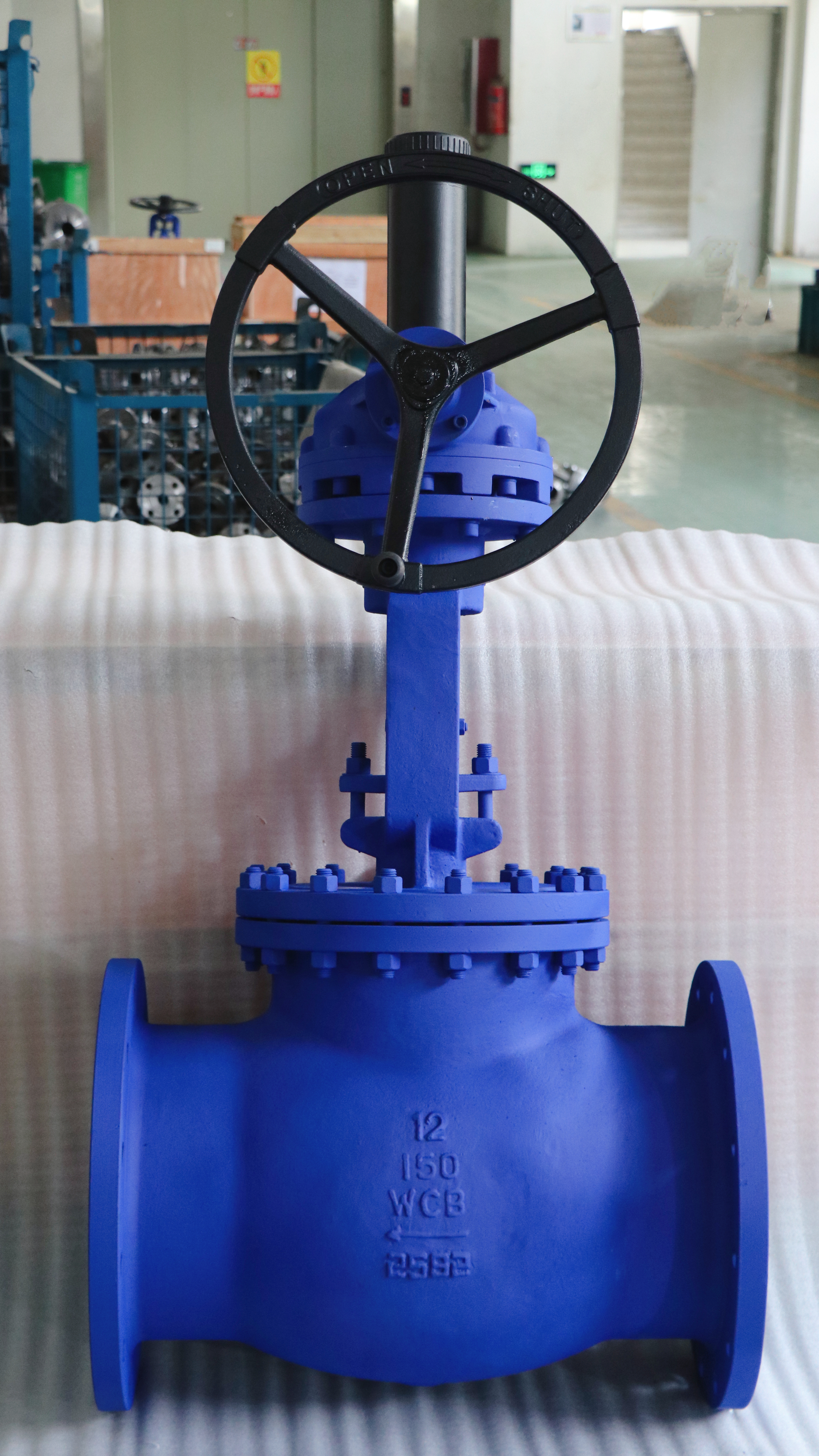
We consider cast iron and carbon steel as the baseline materials for standard utility applications. Cast iron works adequately for low-pressure saturated steam. However, it lacks the tensile strength required for severe thermal shocks. Carbon steel (such as ASTM A216 WCB) provides exceptional durability for medium-pressure steam lines. It handles the structural stress of standard industrial heating processes easily. Most conventional plant utilities rely heavily on carbon steel bodies to distribute energy efficiently across the facility floor.
Standard carbon alloys fall short under extreme conditions. Certain process environments absolutely require advanced metallurgical properties.
Corrosion Resistance: Clean steam systems demand uncompromising purity. Food processing facilities and pharmaceutical plants cannot tolerate rust contamination. Furthermore, returning condensate lines often carry highly acidic water. This corrosive condensate eats through carbon steel rapidly. A stainless steel globe valve provides critical resistance against this chemical attack. The chromium oxide layer prevents degradation, ensuring system longevity and product purity.
Temperature Tolerance: Superheated steam pushes metals to their absolute physical limits. Standard carbon steel becomes susceptible to structural fatigue at extreme temperatures. It also suffers from graphitization over prolonged exposure to high heat. Stainless steel alloys (such as ASTM A351 CF8M) maintain their structural yield strength in superheated environments. They resist thermal deformation and ensure the pressure boundary remains entirely intact.
Consider these standardized steps when evaluating metal grades for your facility:
Identify the exact maximum working pressure (MWP) of the pipeline.
Determine if the system uses saturated steam or superheated steam.
Assess the chemical purity requirements of the downstream manufacturing process.
Analyze the pH level of the returning condensate fluid.
Procuring reliable hardware requires strict adherence to industry standards. Engineers must look beyond physical dimensions. You must evaluate internal geometries, shut-off classifications, and control integration capabilities.
Not all closed valves seal perfectly. The industry defines acceptable shut-off capabilities through standardized FCI (Fluid Controls Institute) and ANSI frameworks. You must define these limits based on the critical nature of your steam line. A Class IV rating permits a tiny, predefined percentage of fluid to bypass the seat. This works fine for basic throttling loops where complete isolation happens elsewhere. Conversely, a Class VI rating utilizes resilient sealing materials for bubble-tight shut-off. Specify Class VI when absolute isolation is required to protect downstream maintenance crews from hot steam.
Many technicians make the fatal error of specifying a Globe Valve purely based on pipe diameter. Matching a 4-inch pipe to a 4-inch valve body often leads to severe operational failure. If the internal orifice is too large, the plug operates too close to the seat. This causes dangerous instability and rapid wear. You must match the valve's Flow Coefficient (Cv) to the specific steam mass flow rate. The Cv represents the exact volume of fluid passing through the body at a specific pressure drop. Proper Cv calculation ensures the plug operates in its optimal middle-travel range.
Modern process control demands flexible actuation options. You must evaluate how operators will interact with the equipment. Manual handwheels work perfectly for bypass lines or isolation points requiring infrequent adjustments. However, automated process control loops demand dynamic responses. Evaluate pneumatic or electric actuation compatibility. Pneumatic actuators offer rapid fail-safe responses, closing instantly during power losses. Electric actuators provide incredibly granular positional feedback for advanced digital control systems.
Ignoring the specific gravity and specific volume changes of superheated steam during Cv calculations.
Over-sizing the internal trim, leading to chattering and premature seat destruction.
Selecting standard packing materials for high-cycle automated control loops.
Even perfectly specified equipment will fail if installed incorrectly. Steam networks require specialized installation knowledge. Understanding fluid dynamics and thermal expansion prevents catastrophic pipeline ruptures.
You cannot install these bodies in random orientations. They possess a highly specific directional geometry. Operators must pay close attention to the critical difference between flow directions. The standard configuration for steam throttling dictates "flow under the seat." The steam pressure pushes up against the plug. This orientation protects the stem packing from constant high pressure when closed. It also ensures smooth throttling. Conversely, some high-pressure shut-off applications require "flow over the seat." Here, the steam pressure physically helps force the plug downward into the seat. However, this orientation complicates precise throttling and stresses the packing material.
Rapidly introducing hot steam into cold pipes creates massive thermal shock. As steam touches cold metal, it instantly condenses into heavy water slugs. The rushing steam accelerates these water slugs to high velocities. When they strike a closed fitting, they generate a massive concussive force called water hammer. This force easily shatters cast iron bodies. You mitigate these risks through proper warm-up bypass lines. Operators crack open a small bypass line to slowly heat the main pipeline. You must also ensure the main valve body can handle rapid thermal cycling without warping.
Industrial components inevitably require servicing. Assessing maintenance accessibility saves countless hours of facility downtime. The top-entry design offers a massive operational advantage. Technicians can unbolt the bonnet and remove the entire internal assembly. This allows operators to replace plugs, machine seats, and upgrade packing materials without ever removing the main body from the steam pipeline. In-line repairability represents a critical feature for welded steam networks.
Always install the stem pointing upright or at a slight angle. Never install it pointing downward, as corrosive condensate will pool inside the bonnet.
Verify the flow direction arrow cast into the metal body matches the pipeline flow.
Install adequate steam traps immediately upstream to remove condensate before it reaches the sealing surfaces.
Globe valves remain entirely non-negotiable for safe, precise steam flow regulation. Their unique linear motion design outclasses generic alternatives, provided you apply correct engineering principles. You must ensure the chosen material, body pattern, and flow coefficient strictly align with your exact system metrics.
To improve your plant's reliability, audit your current steam line failure points today. Inspect existing units for signs of wire drawing or fugitive emissions. Calculate your exact Cv requirements based on mass flow rates, rather than just matching pipe diameters. Finally, consult with a qualified valve manufacturer to shortlist appropriate models, ensuring your next installation delivers peak thermal efficiency and safety.
A: Gate valves are engineered for on/off isolation only. Attempting to throttle high-velocity steam with a gate valve causes immediate seat damage, known as wire drawing, and induces severe mechanical vibration. Globe valves are built specifically for proportional control, using internal geometries that safely manage pressure drops and protect sealing surfaces.
A: No. Stems should generally point upward to prevent corrosive condensate from pooling in the bonnet area. Additionally, the flow direction arrow cast on the body must be strictly followed. For most steam applications, the pipeline must be oriented so that flow travels under the plug.
A: Lifespan heavily depends on the cycle frequency, operating temperature, and actual stroke length. However, high-quality industrial bellows are typically rated to withstand tens of thousands of cycles without failure. Furthermore, a secondary backup graphite packing is always included within the bonnet for ultimate safety and emission control.


