

close
Choose Your Site
Global
Social Media
In high-pressure industrial piping, flow reversal isn't just an operational inconvenience. It is a critical safety hazard. This phenomenon can cause catastrophic equipment damage, sudden water hammer, and devastating system downtime. Standard swing or wafer valves generally suffice for basic utility lines. However, high-velocity, compressible fluids require a significantly different approach. Lift check valves operate similarly to robust globe valves, offering superior sealing capabilities in these demanding environments. Selecting the right Check Valve for high-pressure applications requires careful engineering. You must match the mechanical design and material composition to specific flow media. Evaluating pressure classes and thermal conditions ensures long-term system integrity. Engineers face constant pressure to optimize plant safety. They must carefully avoid specifying incorrect components. We will explore how specific operational realities directly dictate valve selection. You will learn the exact services where lift designs excel. We will also cover material selection guidelines and vital installation best practices.
Lift check valves are optimally designed for high-pressure, high-velocity applications involving compressible fluids like steam, gas, and vapor.
For aggressive media or extreme thermal cycling, specifying a high temperature check valve or a stainless steel check valve is critical to preventing seat deformation and corrosion.
Unlike swing valves, standard lift check valves must typically be installed in horizontal pipelines (unless spring-assisted) and inherently introduce a higher pressure drop due to their tortuous flow path.
System evaluation must balance the need for a tight, leak-proof seal against acceptable flow coefficients (Cv) and maintenance accessibility.
Backflow presents severe mechanical and financial risks in industrial piping. Reverse flow can wreck expensive pumps in seconds. It also triggers compressor surges and dangerous cross-contamination across processing units. You simply cannot ignore these threats. Engineers must design systems capable of halting reverse momentum instantly.
Standard swing valves often fail miserably under these harsh conditions. High-velocity fluids violently batter their internal components. This continuous abuse causes premature wear. Hinge-pins shear off entirely. Rapid seat degradation compromises the entire seal. You cannot rely on them for volatile, high-pressure applications where safety is paramount.
Lift designs provide a distinct structural advantage. They utilize a highly robust globe-style seating mechanism. The internal piston or disc lifts straight up. This movement remains completely perpendicular to the seat. This vertical orientation allows incredibly rapid closure when forward flow stops. It dramatically minimizes slamming under high pressure. The piston guides itself smoothly within the body cavity, reducing lateral vibration.
Engineers measure success through strict performance metrics. A successful deployment demands zero fugitive emissions. You must ensure zero reverse flow during operation. The system requires a perfectly stable cracking pressure. Sustained seat integrity over the lifecycle defines a truly reliable installation. Industry testing protocols, such as API 598, verify these parameters before you install the unit in the field.
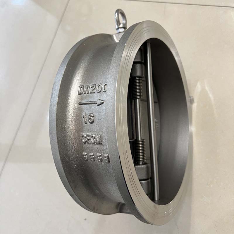
High-pressure steam systems rely heavily on fast-acting flow control. Boiler feed lines and steam condensation recovery networks demand rapid closure. This swift action prevents devastating steam hammer. The robust lift mechanism handles flashing liquids effortlessly. It protects vulnerable boiler components from sudden, violent pressure spikes.
Petrochemical and refining facilities process highly volatile gases constantly. These high-velocity streams require absolute tight shut-off capabilities. Lift valves prevent explosive backflow scenarios in gas processing trains. They maintain strict process isolation where safety margins remain razor-thin. When refining sour gas, the tight internal tolerances prevent hazardous leaks into upstream equipment.
Power generation plants operate under extreme parameters. Facilities utilize heavy-duty ASME Class 900 to 2500 piping for high-pressure feedwater. Main steam lines also demand absolute reliability day and night. In these specific setups, seat integrity is entirely non-negotiable. Lift designs provide the heavy-duty sealing necessary to prevent catastrophic plant trips and safeguard turbines.
Air and gas compressor discharge lines create uniquely hostile environments. Compressors generate violent, pulsating flow patterns naturally. These severe pulsations quickly destroy the delicate hinge pins found in traditional swing valves. Conversely, a piston-style lift valve handles this vibration without suffering internal destruction. The guided piston moves smoothly. It dampens the destructive kinetic energy safely.
Material selection strictly dictates long-term performance in harsh environments. Superheated steam and extreme exothermic chemical processes generate intense thermal stress. You must specify a dedicated high temperature check valve for these severe setups. Forged steel and specialized alloys actively resist thermal creep. These heavy-duty materials prevent galling when internal components expand rapidly under heat. They maintain structural stability when temperatures exceed 800°F.
Corrosive media and strict purity standards require entirely different alloys. Acidic environments and high-chloride services destroy standard carbon steel rapidly. In these demanding cases, installing a stainless steel check valve becomes absolutely mandatory. Common choices include 316SS and specialized Duplex grades. They offer superior resistance to pitting and stress corrosion cracking. Furthermore, facilities needing strict material traceability often mandate NACE MR0175 compliant stainless configurations.
High-velocity media also causes severe mechanical erosion inside the pipeline. Standard seating surfaces wash away under high-pressure gas flows. Hardfaced seating offers the ultimate solution here. Manufacturers frequently apply Stellite overlays to the critical sealing areas. These hardened seats withstand aggressive erosive forces. They ensure tight shut-off for many years, even when handling dirty steam.
Always match your body material to the adjoining pipe schedule to ensure uniform thermal expansion rates.
Request detailed material test reports (MTRs) for high-pressure boundary components.
Specify Stellite trim for any gas service exceeding ASME Class 600.
Using soft seats, like PTFE or elastomers, in services exceeding 400°F.
Ignoring the galvanic corrosion potential between dissimilar internal metals.
Selecting standard austenitic stainless steel for high-chloride environments prone to pitting.
Engineers must evaluate specific trade-offs when choosing between valve types. Let us examine the technical differences between lift and swing mechanisms clearly. You must understand these functional distinctions to ensure plant reliability.
First, consider the state of your media carefully. Swing variants generally perform better for non-pulsating liquids. They allow a relatively straight flow path. However, lift designs clearly dominate in gas, steam, and vapor applications. Their guided discs handle highly compressible fluids exceptionally well. The piston design stabilizes the disc during turbulent flow.
The primary drawback involves the inevitable pressure drop (ΔP). Lift variants feature a tortuous, globe-style flow path internally. The fluid must change direction twice to pass through the main body. This inherently introduces a much higher pressure drop. You must accept this energy trade-off when sealing integrity heavily outweighs pumping efficiency.
Maintenance profiles also differ significantly in the field. Lift variants typically feature a highly convenient top-entry design. This smart configuration allows technicians to service the internal components in-line. You rarely need to remove the heavy body from the pipeline. Alternative types often require complete removal. This heavily complicates routine turnarounds and drastically increases labor costs.
Evaluation Metric | Lift Design | Swing Design |
|---|---|---|
Optimal Fluid State | Steam, Gas, Vapor, Compressible Fluids | Water, Heavy Liquids, Non-Pulsating Media |
Flow Path & Pressure Drop | Tortuous Path (High ΔP) | Straight Path (Low ΔP) |
Resistance to Pulsation | Excellent (Guided Piston) | Poor (Hinge Pin Wear) |
Maintenance Profile | Top-Entry, In-line Servicing | Often requires complete pipeline removal |
Seating Action | Vertical, minimizes slamming | Arc-swing, prone to water hammer |
Proper installation directly determines your operational success. Gravity-operated models possess strict orientation limitations. You must install them in perfectly horizontal lines. The bonnet must face directly upward at all times. Gravity strictly pulls the piston down onto the seat when forward flow ceases. If you install them sideways, they will simply leak profusely. The internal disc will bind against the guide walls.
Vertical installations demand very specific mechanical workarounds. You can install a spring-assisted lift design in vertical pipe runs. The internal spring actively forces the disc closed against gravity. However, exercise extreme caution here. Springs inherently introduce a new point of potential mechanical failure. Severe thermal cycling can rapidly weaken the spring temper over time. This leads to delayed closure and dangerous backflow.
Proper sizing prevents catastrophic internal damage entirely. Never oversize your valve simply to match the adjoining pipe diameter. A unit sized too large for actual flow velocity will chatter violently. The fluid lacks kinetic energy. The disc bounces rapidly against the hard seat. This violent chattering leads to rapid internal destruction. You must evaluate sizing based on minimum flow velocity requirements. The fluid must possess enough energy to keep the disc fully lifted during normal operations.
Engineers often utilize industry guidelines, such as Crane TP-410, to calculate minimum velocities. You must ensure the flow rate pushes the piston to its fully open stop. If it hovers mid-stroke, turbulence will erode the guiding surfaces. Always calculate the specific flow coefficient (Cv) required for your process.
Lift designs remain the undeniable engineering standard for critical industrial services. They excel dramatically in high-pressure, high-velocity steam and gas applications. They consistently deliver the tight shut-off required to prevent dangerous backflow scenarios. You cannot achieve this level of security with standard swing models.
Procurement teams and engineers must align on exact operating parameters before ordering. You need to gather precise data regarding flow rates and media types. Confirm the maximum allowable working pressure and thermal ranges. Calculate your acceptable pressure drop tolerances precisely. Skipping these steps leads to inevitable field failures.
Consulting an application engineer often prevents highly costly mistakes. We strongly encourage requesting a detailed technical quote early. Verify ANSI/ASME class ratings thoroughly. Ensure your chosen metallurgy heavily aligns with system demands. Verify all flow coefficient data before finalizing any procurement. Rigorous pre-planning guarantees reliable, leak-free operation for decades.
A: You can only use them vertically if they feature a specifically engineered spring-loaded design. Standard gravity-reliant models must be installed horizontally with the bonnet facing upward. Otherwise, gravity cannot pull the piston down to create a proper seal.
A: Chattering heavily occurs when you oversize the unit for the system's actual flow rate. The fluid simply lacks sufficient velocity to hold the disc fully open. This causes the internal components to bounce rapidly against the seat, destroying themselves.
A: They feature vastly different body metallurgy, utilizing forged alloy steel or specialized stainless grades. They also utilize hardfaced seating materials like Stellite. Manufacturers engineer them with specific internal tolerances to safely accommodate extreme thermal expansion.
A: No. Their tortuous internal flow path and incredibly tight tolerances make them highly prone to severe clogging. Sticky media quickly jams the guiding piston. Manufacturers design them exclusively for clean, fast-moving gases, steam, and light liquids.


